XBee Interface
The YRL Expansion Board has an interface for Digi XBee modules, allowing various additional forms of wireless communication between robots, such as ad hoc point-to-point or mesh networking.
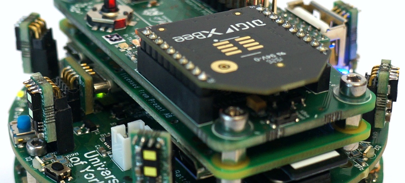
The interface pinout is compatible with any through-hole XBee or XBee-PRO module, but has primarily been tested with the 2.4GHz/Zigbee 3.0 XBee 3 with PCB antenna. A good source of information on the various available XBee modules is the SparkFun XBee Buying Guide.
Using the XBee
The XBee is accessible using a USB UART interface from Linux on the Raspberry Pi, typically mapped to /dev/ttyUSB0.
The USB device uses port 3 on bus 1, and has ID 0403:6015, as shown by the following output from lsusb.
Bus 001 Device 004: ID 0403:6015 Future Technology Devices International, Ltd Bridge(I2C/SPI/UART/FIFO)
Bus 001 Device 003: ID 0403:0fd8 Future Technology Devices International, Ltd
Bus 001 Device 002: ID 0424:2513 Standard Microsystems Corp. 2.0 Hub
Bus 001 Device 001: ID 1d6b:0002 Linux Foundation 2.0 root hub
/:  Bus 01.Port 1: Dev 1, Class=root_hub, Driver=dwc_otg/1p, 480M
    |__ Port 1: Dev 2, If 0, Class=Hub, Driver=hub/3p, 480M
        |__ Port 1: Dev 3, If 1, Class=Video, Driver=uvcvideo, 480M
        |__ Port 1: Dev 3, If 0, Class=Video, Driver=uvcvideo, 480M
        |__ Port 3: Dev 4, If 0, Class=Vendor Specific Class, Driver=ftdi_sio, 12M
While the Raspberry Pi does not support the standard Digi XCTU configuration utility for XBee hardware, AT commands can be sent manually over the USB UART interface, and programming libraries are available for a number of languages:
Digi XBee Python library - https://github.com/digidotcom/xbee-python
Digi XBee C library https://github.com/digidotcom/xbee_ansic_library
Digi XBee Java library - https://github.com/digidotcom/xbee-java
Digi XBee C# library - https://github.com/digidotcom/xbee-csharp
The YRL Expansion Board GitHub repository contains a number of example scripts for setting up and programming the firmware of the XBee using Python.
Hardware Design
The XBee interface hardware is based on the SparkFun XBee Explorer USB design, including an FT231X USB UART controller for communication with the Raspberry Pi, and LEDs for indicating data transfer on both the UART and wireless sides. Similar to the XBee Explorer, marked exposed traces can be cut (or rejoined) on the underside of the PCB for isolating RSSI, DTR, RTS and CTS signals if required.